Machine Shop / Locomotive Drive Work
-
bob turner
- Posts: 13596
- Joined: Sat Jan 13, 2007 7:57 pm
Re: Machine Shop / Locomotive Drive Work
I think that at least the Cotton Belt had 70” drivered Atlantics, and maybe the TNO as well. I shall check.
-
R.K. Maroon

- Posts: 3132
- Joined: Tue Feb 22, 2011 9:20 pm
Re: Machine Shop / Locomotive Drive Work
The websites steamlocomotive.com and espee.railfan.net provide the following information:
Locomotive #275 was one of five class A-1 Atlantics on the T&NO roster, part of a group of sixteen built by Baldwin in 1902 for the SP and T&NO. They were originally built as Vauclain compounds, but converted by T&NO in 1925 to simple expansion as part of a rebuild. Here is some of the data provided:

The drivers were originally 77" but the T&NO five were equipped with 73" diameter drivers as part of the 1925 rebuild. These appear to be the smallest drivers of all the SP Atlantics. I will measure the drivers of the model the next time I am at the shop.
The T&NO Atlantics worked through the war but scrapped shortly thereafter.
Here are the links to the referenced websites:
https://www.steamlocomotive.com/locobase.php?country=USA&wheel=4-4-2&railroad=sp#11
http://espee.railfan.net/sp_steam_a-01-1.html
Jim
Locomotive #275 was one of five class A-1 Atlantics on the T&NO roster, part of a group of sixteen built by Baldwin in 1902 for the SP and T&NO. They were originally built as Vauclain compounds, but converted by T&NO in 1925 to simple expansion as part of a rebuild. Here is some of the data provided:
The drivers were originally 77" but the T&NO five were equipped with 73" diameter drivers as part of the 1925 rebuild. These appear to be the smallest drivers of all the SP Atlantics. I will measure the drivers of the model the next time I am at the shop.
The T&NO Atlantics worked through the war but scrapped shortly thereafter.
Here are the links to the referenced websites:
https://www.steamlocomotive.com/locobase.php?country=USA&wheel=4-4-2&railroad=sp#11
http://espee.railfan.net/sp_steam_a-01-1.html
Jim
The link below any photo will display the image full size
-
bob turner
- Posts: 13596
- Joined: Sat Jan 13, 2007 7:57 pm
Re: Machine Shop / Locomotive Drive Work
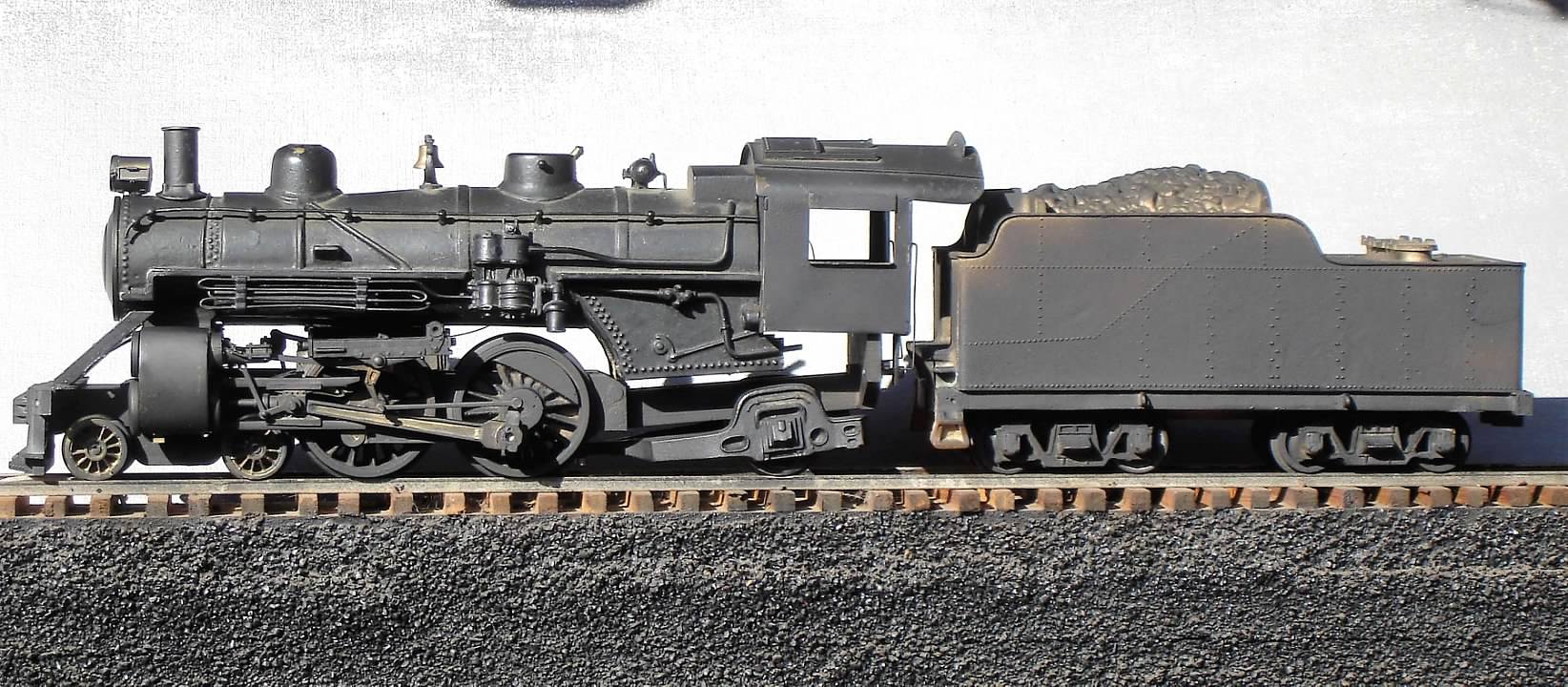
I am going to repeat Jim's Atlantic, then post an All Nation sort-of stock version. Let me see if this works:

-
bob turner
- Posts: 13596
- Joined: Sat Jan 13, 2007 7:57 pm
Re: Machine Shop / Locomotive Drive Work
Yes, it worked. I am not a great fan of the All Nation models, except for the Mountain, but I have one of each, in various forms of disarray and modification. I think this one could be saved with an extended firebox, new cab mounted slightly further aft, and a new smokebox wrapper extending that part forward maybe 1/8" or so. The taper is correct for the TNO class A-2, but you can see that Jim's model has a far more graceful appearance.
Not going to tackle that tonight - I pulled out the SE-3 and may add running boards. It runs, but is currently pretty ugly.
Not going to tackle that tonight - I pulled out the SE-3 and may add running boards. It runs, but is currently pretty ugly.
-
R.K. Maroon
- Posts: 3132
- Joined: Tue Feb 22, 2011 9:20 pm
Re: Machine Shop / Locomotive Drive Work
Here is a different view of the comparison that Bob made above regarding the two Atlantics:

I flipped Bob's photo 180 degrees, so what looks like the engineer's side is actually the fireman's side. This view makes it easier (at least for me) to see the differences, which are many.
I took calipers to the drivers of the T&NO model today. They measured out to 70", which is a bit smaller than the 73" of the prototype. The drivers on the model appear to be stock, but I didn't think to check them against the one and only other GMC-All Nation model I own (an articulated).
Jim
I flipped Bob's photo 180 degrees, so what looks like the engineer's side is actually the fireman's side. This view makes it easier (at least for me) to see the differences, which are many.
I took calipers to the drivers of the T&NO model today. They measured out to 70", which is a bit smaller than the 73" of the prototype. The drivers on the model appear to be stock, but I didn't think to check them against the one and only other GMC-All Nation model I own (an articulated).
Jim
The link below any photo will display the image full size
-
bob turner
- Posts: 13596
- Joined: Sat Jan 13, 2007 7:57 pm
Re: Machine Shop / Locomotive Drive Work
All of the AN drivers are 70", from the American through the articulated. The counterweights are B&O ten wheeler.
I decided to work on it a bit. First step will be extending the smokebox, possibly as much as 3/8". That will allow me to re-drill the forward cylinder mounting screw and stack holes in new metal, and will move the firebox aft 1/8".
Then new firebox sheets. One side has the reverser cast in, and I will leave it that way (doorstop heritage, right?).
It will get a new cab, which will look a lot more like Jim's, but I am going to copy the cab from a prototype photo.
And finally, it will get new dome tops, more in keeping with SP contours. I may re-do the cooling coils, but not until I see if I can create the grace of the A-1. Oh, and it will get a boiler belly. Mine already has 72" drivers (Lobaugh). They fit right in the AN frame, even though I generally recycle those in favor of 1/4" brass plate.
Thanks! Makes it lots easier to compare.
I decided to work on it a bit. First step will be extending the smokebox, possibly as much as 3/8". That will allow me to re-drill the forward cylinder mounting screw and stack holes in new metal, and will move the firebox aft 1/8".
Then new firebox sheets. One side has the reverser cast in, and I will leave it that way (doorstop heritage, right?).
It will get a new cab, which will look a lot more like Jim's, but I am going to copy the cab from a prototype photo.
And finally, it will get new dome tops, more in keeping with SP contours. I may re-do the cooling coils, but not until I see if I can create the grace of the A-1. Oh, and it will get a boiler belly. Mine already has 72" drivers (Lobaugh). They fit right in the AN frame, even though I generally recycle those in favor of 1/4" brass plate.
Thanks! Makes it lots easier to compare.
-
bob turner
- Posts: 13596
- Joined: Sat Jan 13, 2007 7:57 pm
Re: Machine Shop / Locomotive Drive Work
First step is done - extending the smokebox dramatically changes things.
There are limits to making doorstops more realistic - lots easier to start from scratch.
There are limits to making doorstops more realistic - lots easier to start from scratch.
-
bob turner
- Posts: 13596
- Joined: Sat Jan 13, 2007 7:57 pm
Re: Machine Shop / Locomotive Drive Work
I am stopping here - needs a new cab, stack, headlight, and lots of piping/appurtenances. But I am going to mess with the SE-4 0-8-0 for a while.

-
ScaleCraft

- Posts: 6693
- Joined: Thu Jan 26, 2012 10:15 pm
Re: Machine Shop / Locomotive Drive Work
R.K. Maroon wrote:Here is a different view of the comparison that Bob made above regarding the two Atlantics:
I flipped Bob's photo 180 degrees, so what looks like the engineer's side is actually the fireman's side. This view makes it easier (at least for me) to see the differences, which are many.
I took calipers to the drivers of the T&NO model today. They measured out to 70", which is a bit smaller than the 73" of the prototype. The drivers on the model appear to be stock, but I didn't think to check them against the one and only other GMC-All Nation model I own (an articulated).
Jim
You know, personally I have never liked the 4-4-2's. Just look...unbalanced. Maybe it comes from the disaster of a Half 0 Roundhouse I had 60 years ago.
But that second one makes me re-evaluate my ideas on 4-4-2's. That one looks more "balanced", drivers more centered under full boiler.
Dave....gone by invitation
-
Rufus T. Firefly

- Posts: 42106
- Joined: Wed May 16, 2007 7:52 am
- Location: To be Determined
Re: Machine Shop / Locomotive Drive Work
bob turner wrote:I am stopping here - needs a new cab, stack, headlight, and lots of piping/appurtenances. But I am going to mess with the SE-4 0-8-0 for a while.
Do like those tender trucks with the spoked wheels.
Evil cannot create anything new, it can only corrupt and ruin what good forces have created or made.
-
R.K. Maroon
- Posts: 3132
- Joined: Tue Feb 22, 2011 9:20 pm
Re: Machine Shop / Locomotive Drive Work
It has been over two weeks since my last post on the T&NO Atlantic. As last reported, I got it assembled but had to wait until the club layout was back up and running. That happened two Saturdays ago. The locomotive again showed a problem with the tender drive -- specifically, the ball-and-socket universal joint would not stay engaged. It took a bit of head scratching and "trying-this, adjusting-that", but I finally concluded that the motor mounts were inadequate. In particular, the mounts did not hold the motor firmly enough under load. I failed to get a "before" photo but this "after" photo shows how the motor is mounted:

As you can see, the motor is mounted on a pair of U-shaped brackets. These are secured to the mount of the tender shell with machine screws -- one screw each, right in the middle. The front bracket here has been replaced. Here is a photo showing the old bracket in front and the new bracket behind, shown bent but not bored:

The as-arrived bracket is made of very thin sheet brass. It seems that the motor on this bracket would give so much under load that the ball-and-socket would pop out. The problem was most acute in curves, as the universal joint bends to the angle of the curve, resulting in a large lateral load from the universal joint onto the motor mount. This is my theory, at any rate. I fabricated a new front bracket. It's much stiffer. I could bend the old bracket easily by hand, but I had to use a bending tool to form the new bracket. I now have this bracket fitted, the motor installed and the locomotive reassembled. I got this far a week ago but have been out of town since. I am back now and have a test run scheduled for tomorrow. Stay tuned.
As an aside, it found it much harder to get the new bracket symmetrically bent to the correct shape than I anticipated. Part of the challenge was the tight space between the motor and the curved profile of the Vanderbilt tender, which required that the bracket be bent accurately. I would create tooling to do this if I had to fabricate more than one or two of these.
Jim
As you can see, the motor is mounted on a pair of U-shaped brackets. These are secured to the mount of the tender shell with machine screws -- one screw each, right in the middle. The front bracket here has been replaced. Here is a photo showing the old bracket in front and the new bracket behind, shown bent but not bored:
The as-arrived bracket is made of very thin sheet brass. It seems that the motor on this bracket would give so much under load that the ball-and-socket would pop out. The problem was most acute in curves, as the universal joint bends to the angle of the curve, resulting in a large lateral load from the universal joint onto the motor mount. This is my theory, at any rate. I fabricated a new front bracket. It's much stiffer. I could bend the old bracket easily by hand, but I had to use a bending tool to form the new bracket. I now have this bracket fitted, the motor installed and the locomotive reassembled. I got this far a week ago but have been out of town since. I am back now and have a test run scheduled for tomorrow. Stay tuned.
As an aside, it found it much harder to get the new bracket symmetrically bent to the correct shape than I anticipated. Part of the challenge was the tight space between the motor and the curved profile of the Vanderbilt tender, which required that the bracket be bent accurately. I would create tooling to do this if I had to fabricate more than one or two of these.
Jim
The link below any photo will display the image full size
-
bob turner
- Posts: 13596
- Joined: Sat Jan 13, 2007 7:57 pm
Re: Machine Shop / Locomotive Drive Work
I think I have six "tender drive" models.
The secret: a large NWSL horney ball set (G scale size), a short length of Toyota hose, a Pittman 8000 series motor, some aircraft safety wire, and a short section of 2" bar rail.
The worm shaft needs to be supported as close to the rear of the cab as possible, with the ball pressed on at roughly the rotation point between locomotive and tender.
The motor is secured in a tray made from bar rail, anchored low in the tender bed. You want a straight shot from motor shaft to worm shaft. Use safety wire and rubber cushions to secure the motor.
The Toyota hose goes on the motor shaft, and the cup goes on the forward end of the hose. The hose is not there to flex; just to keep the noise down.
The drawbar is set up so the tender can be separated without removing screws. One of the tender trucks needs to be laterally stabilized. The only problem I ever encountered with this setup is tender wrap-up.
I know this is pretty much different from any setup you have seen, but it works! Really necessary for Harriman switchers and ten-wheelers. Want a sketch? Or a photo of one, disassembled?
The secret: a large NWSL horney ball set (G scale size), a short length of Toyota hose, a Pittman 8000 series motor, some aircraft safety wire, and a short section of 2" bar rail.
The worm shaft needs to be supported as close to the rear of the cab as possible, with the ball pressed on at roughly the rotation point between locomotive and tender.
The motor is secured in a tray made from bar rail, anchored low in the tender bed. You want a straight shot from motor shaft to worm shaft. Use safety wire and rubber cushions to secure the motor.
The Toyota hose goes on the motor shaft, and the cup goes on the forward end of the hose. The hose is not there to flex; just to keep the noise down.
The drawbar is set up so the tender can be separated without removing screws. One of the tender trucks needs to be laterally stabilized. The only problem I ever encountered with this setup is tender wrap-up.
I know this is pretty much different from any setup you have seen, but it works! Really necessary for Harriman switchers and ten-wheelers. Want a sketch? Or a photo of one, disassembled?
Last edited by bob turner on Thu Nov 10, 2022 1:39 pm, edited 1 time in total.
-
bob turner
- Posts: 13596
- Joined: Sat Jan 13, 2007 7:57 pm
Re: Machine Shop / Locomotive Drive Work
Ah - your photos just showed up. It is that U joint that is the problem. Replace it with fairly rigid hose.
My Vanderbilt tenders start with bar rail. The motor is anchored inside the 2" tube with a pair of screws up from the bottom into the inside segment of bar rail.
My Vanderbilt tenders start with bar rail. The motor is anchored inside the 2" tube with a pair of screws up from the bottom into the inside segment of bar rail.
-
bob turner
- Posts: 13596
- Joined: Sat Jan 13, 2007 7:57 pm
Re: Machine Shop / Locomotive Drive Work
While we are on Atlantics, Lionel has a fairly new offering that looks a bit like the above-discussed models. It is tempting to lift a photo out of OGR, but then I would be a hypocrite.
Right now they are complaining about paint colors - specifically Southern Green - but I am struck by how much the boiler casting looks like the SP Atlantic series. The mechanism appears to be a PRR E6 component, but the domes, cab, and stack are all SP. Looks a lot better than my cobbled together All Nation.
Made a new stack last night - too big. I think another is in order this morning before departing for the airport.
Right now they are complaining about paint colors - specifically Southern Green - but I am struck by how much the boiler casting looks like the SP Atlantic series. The mechanism appears to be a PRR E6 component, but the domes, cab, and stack are all SP. Looks a lot better than my cobbled together All Nation.
Made a new stack last night - too big. I think another is in order this morning before departing for the airport.
-
ScaleCraft
- Posts: 6693
- Joined: Thu Jan 26, 2012 10:15 pm
Re: Machine Shop / Locomotive Drive Work
bob turner wrote: It is tempting to lift a photo out of OGR, but then I would be a hypocrite.
Right click on the photo. Copy image location. Post that URL here, if folks want to look, they click on the link. No photos hot-linked. Easy. I do it all the time.
This one?
https://ogrforum.ogaugerr.com/fileSendA ... G_0531.JPG

Dave....gone by invitation
Return to “O-Gauge, 2-Rail, Model Railroading”
Who is online
Users browsing this forum: Baidu [Spider] and 47 guests