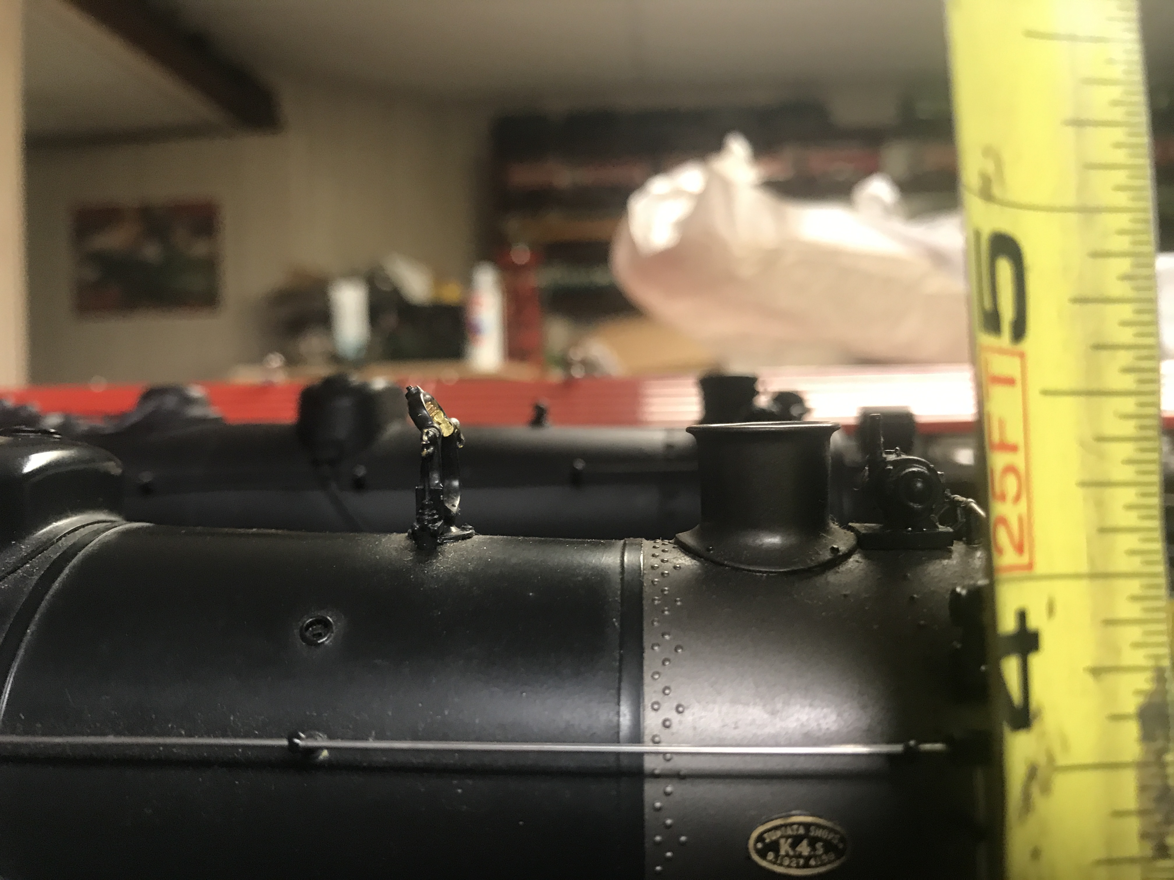
scalecraft K4 rehab some questions
-
Dennis Holler
- Posts: 455
- Joined: Mon Dec 13, 2010 8:31 pm
scalecraft K4 rehab some questions
I've got a few of these beasts and been digging into two of the three. I've got both the center drive and the rear axle drive. Right now I'm focusing on the most recent one which came with what I think are Lobaugh Boxpok drivers. I realize I may be very wrong about that source, but so far that's my best guess. I've curious to see if you all can get me squared away on that driver source. Also looks like the builder did use the 1/4" dia axles in the frame turned down to 3/16ths for the wheels, also look like the little keys are present for quartering. Honestly I don't really mind them and will keep them on the loco for now. However, in the future, I'd like the install some more correct PRR drivers. At this point I think I've got the valve gear straightened out so that it is good and smooth. Right now the thing that is annoying me is the noise coming from the angle drive bearing block. As you guys know, the stub end of the worm shaft rides on a ball bearing and in the bronze block. The top (motor) end also rides in the block. Couple of things I noticed. 1) That top end bearing is sloppy, 2) The tee pin on the motor shaft was originally too long or wide so to speak and as such as been dragging on the inner surface of that block as the motor shaft spun. Filing the pin down so it no longer rubbed was easy. that actually quieted things quite a bit. It is probably fine as is but I am interested in improving things further. So at this point, the question is have any of you installed a ball bearing on the top end of that worm drive block. I've found a 3/16ths ID 5/16ths OD plus a shoulder. I think that would completely solve problem. Taking that a step further, it looks like I could similarly install the 1/4" ID version of the same bearings on the axles. The frame casting is thick enough and tall enough to accept the necessary machining operation. What are your thoughts? Obviously, I don't want to trash it but I don't think it will be that bad to work through either. I should be able to set the frame up on my lathe tool post for the axle bores and locate that way. For the bearing block since it is on an angle, I was thinking of using a spotface cutter if I could find the right diameters. I just wanted to bounce the idea and see what experience or ideas you all might have before I make some chips.
Doorstop Rookie
-
bob turner
- Posts: 13596
- Joined: Sat Jan 13, 2007 7:57 pm
Re: scalecraft K4 rehab some questions
Don't do it. If you want the best drive ever, put a big can motor in there, and replace that U joint with Toyota hose. The rear axle drive works ok, but the center deal is dead-smooth.
Lobaugh drivers have shouldered axles. If you want spoked, Joe can machine a set for you to fit 1/4" axles. He knows where to get the blanks. Real K4 drivers are straight line counterweights, and a bit harder to find.
-
Dennis Holler
- Posts: 455
- Joined: Mon Dec 13, 2010 8:31 pm
Re: scalecraft K4 rehab some questions
Thanks Bob, on the drivers, I see that Stevenson Preservation has several varieties of PRR 80" drivers listed including Baldwin disc. Looks like any of those come without the tire, is that correct?
When you guys center drill your axles, what size center drill are you using? The smallest I see with just light searching is 1/32".
I have collets and a collet stop so I think I should be able to turn uniform length axles and such. No keys though.
Do you use any additional interference on your wheel to axle fit or do you just go .1875 for the bore and axle plus a bit of Loctite? Just curious, I suspect it does not take much.
The hose is a great idea for the top frame with center drive. I may do a can on one someday, but for now, I'm still reluctant to... maybe I'm being to cheap.
I also notice the flange height on those Lobaugh drives is pretty minimal, like 0.030 or so. What would be the min flange height you guys would go for a loco to run on crappy code 148 rail for example?
Sorry for all the questions but each of these locos has been set up differently. The lobaugh driver one seems to have been machined at the old NMRA standards, but the other two not so much.
Bob, do you have any close ups of your scalecraft frames? Anyone else please post as well. I've been looking at the old thread for the K4 that Allan had Joe work on the wheels as reference.
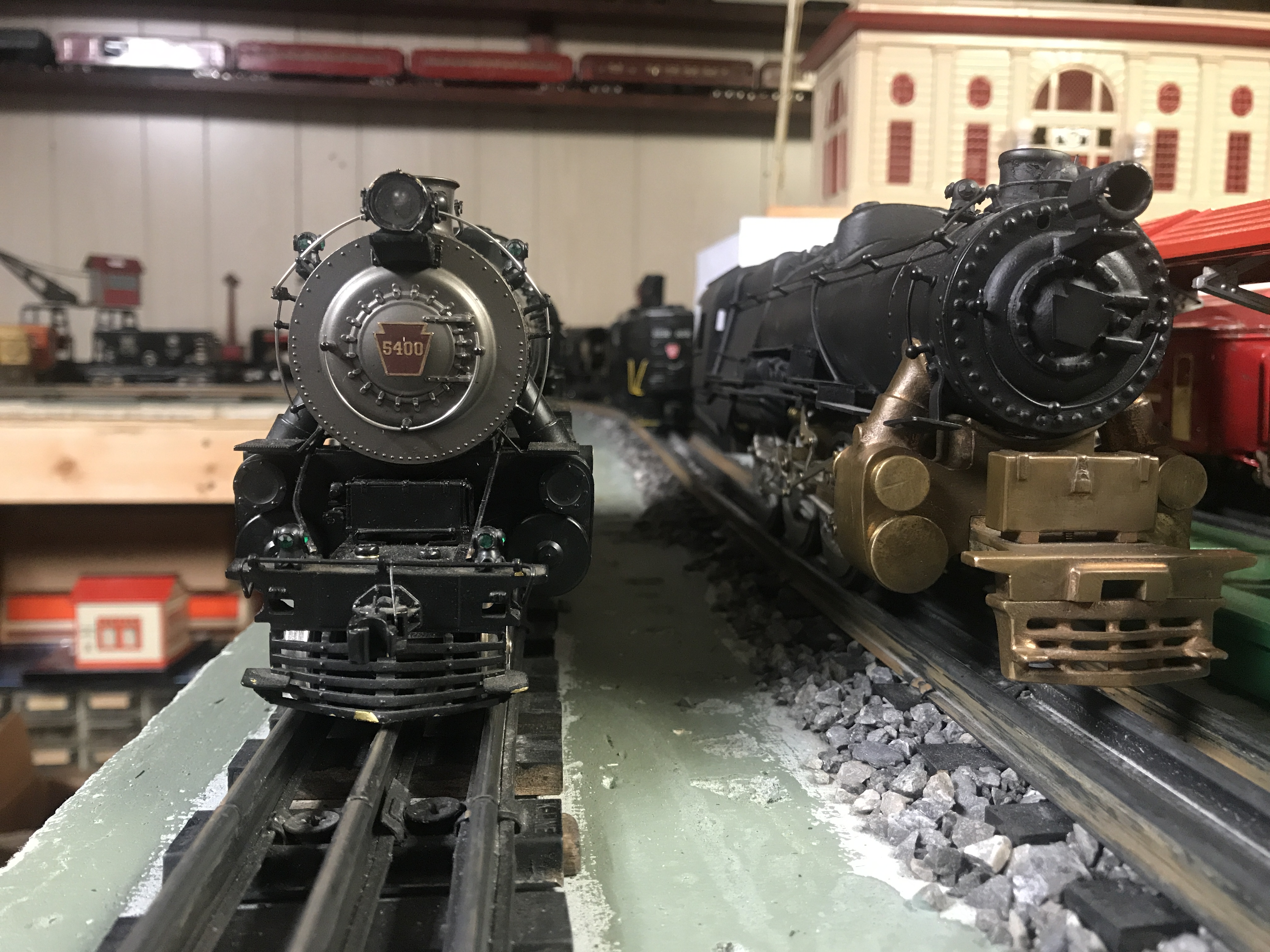
Also, for my own reference are all these SX K4's considered to be somewhat 17/64th's? These tower above my Williams K4 although there are barely longer or wider.
When you guys center drill your axles, what size center drill are you using? The smallest I see with just light searching is 1/32".
I have collets and a collet stop so I think I should be able to turn uniform length axles and such. No keys though.
Do you use any additional interference on your wheel to axle fit or do you just go .1875 for the bore and axle plus a bit of Loctite? Just curious, I suspect it does not take much.
The hose is a great idea for the top frame with center drive. I may do a can on one someday, but for now, I'm still reluctant to... maybe I'm being to cheap.
I also notice the flange height on those Lobaugh drives is pretty minimal, like 0.030 or so. What would be the min flange height you guys would go for a loco to run on crappy code 148 rail for example?
Sorry for all the questions but each of these locos has been set up differently. The lobaugh driver one seems to have been machined at the old NMRA standards, but the other two not so much.
Bob, do you have any close ups of your scalecraft frames? Anyone else please post as well. I've been looking at the old thread for the K4 that Allan had Joe work on the wheels as reference.
Also, for my own reference are all these SX K4's considered to be somewhat 17/64th's? These tower above my Williams K4 although there are barely longer or wider.
Doorstop Rookie
-
Dennis Holler
- Posts: 455
- Joined: Mon Dec 13, 2010 8:31 pm
Re: scalecraft K4 rehab some questions
While I'm at it, here are the starting points for these. The first one I got was in pieces with the frame built up. I'm not sure if it was a factory built up frame or not. One thing I notice is that the motor mounting holes place the motor shaft considerably lower than the worm gear shaft centerline which puts the spring drive under a bit of a bind. The Toyota hose would probably help that but raising the motor up would as well. I'll get some hose and check that out though. It has the stock SC Cresent drivers like most of them and not 2 railed as far as I can tell.
The next was this all black one with rear axle drive. It was two railed and came with a Permag motor. It did run but was rough with some binding. The wheels were machined all over the place, with some being .020" wider than others the gauge was all jacked up. It has straight counterweight drivers, but only 15 spoke and they were machined to 1.603" or so which is a good bit short of a scale 80". The tires and flanges are all out of whack to each other as well. I think can save them but they might just be an experiment. The boiler to firebox joint isn't too bad but not too good either. I'll probably just leave it as is for now... It needs some paint though.
Last is this new one with the Lobaugh drivers. It was complete but had a bit of binding in the valve gear. Work in progress I guess.
I suppose I have visions of grandure, but for now they are all just piles of junk waiting for me.
The next was this all black one with rear axle drive. It was two railed and came with a Permag motor. It did run but was rough with some binding. The wheels were machined all over the place, with some being .020" wider than others the gauge was all jacked up. It has straight counterweight drivers, but only 15 spoke and they were machined to 1.603" or so which is a good bit short of a scale 80". The tires and flanges are all out of whack to each other as well. I think can save them but they might just be an experiment. The boiler to firebox joint isn't too bad but not too good either. I'll probably just leave it as is for now... It needs some paint though.
Last is this new one with the Lobaugh drivers. It was complete but had a bit of binding in the valve gear. Work in progress I guess.
I suppose I have visions of grandure, but for now they are all just piles of junk waiting for me.
Doorstop Rookie
-
bob turner
- Posts: 13596
- Joined: Sat Jan 13, 2007 7:57 pm
Re: scalecraft K4 rehab some questions
Elongate the motor mount holes and straighten the drive shaft. Original motor and coupling will give you excellent service - a Pittman/ Toyota hose will make it slightly quieter and snoother. The can motor can be mounted in a tray using old rubber sheets and aircraft safety wire. My trays are just leftover segments of old boiler material.
Scalecraft made both types of drivers - the SP and NYC got the crescent counterweights. A Dremel tool and a very steady hand will convert the counterweights.
Yes - closer to 17/64. The SP was seriously oversize. Tender was closer to 1/4" scale.
Light press fit, and then green Loctite. Makes it easier to quarter. Lobaugh keys are often not good enough for accurate quarter.
What kind of lathe?
Scalecraft made both types of drivers - the SP and NYC got the crescent counterweights. A Dremel tool and a very steady hand will convert the counterweights.
Yes - closer to 17/64. The SP was seriously oversize. Tender was closer to 1/4" scale.
Light press fit, and then green Loctite. Makes it easier to quarter. Lobaugh keys are often not good enough for accurate quarter.
What kind of lathe?
-
Dennis Holler
- Posts: 455
- Joined: Mon Dec 13, 2010 8:31 pm
Re: scalecraft K4 rehab some questions
Thanks Bob. It's a Rockwell 11X48 metal lathe. No taper attachment though. And I still need to find a decent 90 degree vise for the saddle so I can try and use it to mill a few things. I've done a few minor milling tasks by clamping the work in the Aloris AXA-1 tool holder and that has worked for simple holes and such. I see the Indian or Chinese vises on line. Not sure I want to buy a new one of those or a used vintage one. I mentioned the collet set up. I do need to stock up on collets. It's nothing great for sure but it runs fairly well. I need to buy a back plate fro the 4 jaw chuck at some point as well. I also have the face plate for it. This lathe uses the L00 taper lock and not the D camloc for the chuck so any new chuck I'd get would need to be able to mount L00 on it's own or bolt to a back plate. Like I said, it ain't great, but it is a decent lathe and the price was right. I used to teach one of the beginning machine classes for the MET's at my local college 20 years ago. As they would update equipment of course they would kick the old stuff out. That is how I got this Rockwell. The college got a new Hardinge toolroom lathe and so this became surplus. Would have been nice to stay there for a while -I was able to make what ever I wanted for the most part-but the pay wasn't that great so I ended up going back to the real world for better pay.
Btw, since the first post, I worked on the drive some more and I think I'll leave it be for now. (Talking about the Boxpoc rear axle drive chassis now).
So do you think these are Scalecraft castings?
I know the next (partial) set is not... too bad I only have the five and not six...
Don't know where the second set came from....
Btw, since the first post, I worked on the drive some more and I think I'll leave it be for now. (Talking about the Boxpoc rear axle drive chassis now).
So do you think these are Scalecraft castings?
I know the next (partial) set is not... too bad I only have the five and not six...
Don't know where the second set came from....
Doorstop Rookie
-
bob turner
- Posts: 13596
- Joined: Sat Jan 13, 2007 7:57 pm
Re: scalecraft K4 rehab some questions
You are ready. Machine six tires. Use the Lobaugh for sizes.
Then machine the "button" to fit whatever collet you have. When you turn the driver around, make sure the rim is concentric. It usually is, because most castings are dimensionally pretty good. If they do not cut like hot butter, they need to be annealed.
First cut is the face cut. Just remove the scale and get a smooth surface on CWT and crankpin boss.
Second cut is the rim. It goes deeper than the first cut. How much is a matter of taste, but use Lobaugh as a guide.
Third cut is a very small square groove, separating rim from CWT. Again, use Lobaugh as your guide.
Three of your castings can be machined to match your tires. I recommend that - the cast iron is a lot like traction tires. It "grabs!"
The other three get trimmed to accept paper insulation and tires.
Bore the axle holes with a center drill, then a good solid crankshaft drill (short). Bore the crankpin holes with a jig!
Facing the back is the last step. You can do that in the 3-jaw. It isn't critical, but use care to keep it parallel to the face cuts.
Good luck!
Then machine the "button" to fit whatever collet you have. When you turn the driver around, make sure the rim is concentric. It usually is, because most castings are dimensionally pretty good. If they do not cut like hot butter, they need to be annealed.
First cut is the face cut. Just remove the scale and get a smooth surface on CWT and crankpin boss.
Second cut is the rim. It goes deeper than the first cut. How much is a matter of taste, but use Lobaugh as a guide.
Third cut is a very small square groove, separating rim from CWT. Again, use Lobaugh as your guide.
Three of your castings can be machined to match your tires. I recommend that - the cast iron is a lot like traction tires. It "grabs!"
The other three get trimmed to accept paper insulation and tires.
Bore the axle holes with a center drill, then a good solid crankshaft drill (short). Bore the crankpin holes with a jig!
Facing the back is the last step. You can do that in the 3-jaw. It isn't critical, but use care to keep it parallel to the face cuts.
Good luck!
-
Dennis Holler
- Posts: 455
- Joined: Mon Dec 13, 2010 8:31 pm
Re: scalecraft K4 rehab some questions
Thank you Bob! I'll try to get my butt our in the garage and start making some chips. I have a couple of orphan drivers so I'll kill them first for practice. 
Doorstop Rookie
-
Nortonville Phil
- Posts: 214
- Joined: Sat Jul 31, 2010 11:05 pm
- Location: Red Oak TX
- Contact:
Re: scalecraft K4 rehab some questions
Dennis and Bob,
This is an interesting thread. Thanks for the tips on turning drivers. Dennis, I may have a 6th driver that matches those 5 orphans you have. Tell me what the diameter is of the rough casting and I will check.
Trinity Valley Traction Co.
Texas Midland Railroad
Homewood Shops
Red Oak, TX
My traction blog: Bluebonnet Limited
http://bluebonnetlimited.blogspot.com/
Homewood Shops YouTube:
https://youtube.com/@cug6?si=BCFnDDtUw2eVKamo
Texas Midland Railroad
Homewood Shops
Red Oak, TX
My traction blog: Bluebonnet Limited
http://bluebonnetlimited.blogspot.com/
Homewood Shops YouTube:
https://youtube.com/@cug6?si=BCFnDDtUw2eVKamo
Re: scalecraft K4 rehab some questions
Dennis,
When I machine a set of new drivers from iron or bronze castings, I ream the driver axle hole with a precision straight flute HSS reamer that is 0.001" under the axle diameter making a nice press fit. Once center drilled, re-drill the axle hole with a good drill bit 1/64" smaller in diameter than the axle and then ream to size. I also use Loctite 609 Retaining Compound on the connection as Bob mentions above. As far as center drilling the driver castings I often use the No 0 center drills but you can use a larger one that has a body smaller than you axle. I don't think it will matter.
Getting the crank pins accurately drilled into the crank pin bosses is also very important. I made a jig years ago that is fixed to my milling table with clamps. It is a flat piece of 1'2" tool steel with a piece of drill rod the size of the axle mounted to it. The drill rod extends upward to be held in a Jacobs chuck in the spindle of the milling machine. Once the chucked piece of drill rod is released from the drill chuck, the milling machine table with the clamped down jig is dialed out to the crank pin throw desired and a No. 0 center drill is used to start the crank pin holes in the driver casting's crankpin bosses. This results in all of the crank pins being accurately located at the exact same crank pin throw. You can remove the center drill bit after starting each hole and final drill the crank pin hole using the correct size drill bit and reamer to match your crank pin diameter, I Loctite my crankpins into the driver castings. I do not machine as many drivers from rough castings as I do reworking 3 rail drivers that have accurately located crank pins but when I do machine rough castings this method has worked well for me.
Regarding driver tire insulation, I use 0.010" "fish paper" to insulate my driver tires. McMaster Carr is a good in line source of this material. Loctite 609 adheres to it.
Have fun and take your time with this.
Joe
When I machine a set of new drivers from iron or bronze castings, I ream the driver axle hole with a precision straight flute HSS reamer that is 0.001" under the axle diameter making a nice press fit. Once center drilled, re-drill the axle hole with a good drill bit 1/64" smaller in diameter than the axle and then ream to size. I also use Loctite 609 Retaining Compound on the connection as Bob mentions above. As far as center drilling the driver castings I often use the No 0 center drills but you can use a larger one that has a body smaller than you axle. I don't think it will matter.
Getting the crank pins accurately drilled into the crank pin bosses is also very important. I made a jig years ago that is fixed to my milling table with clamps. It is a flat piece of 1'2" tool steel with a piece of drill rod the size of the axle mounted to it. The drill rod extends upward to be held in a Jacobs chuck in the spindle of the milling machine. Once the chucked piece of drill rod is released from the drill chuck, the milling machine table with the clamped down jig is dialed out to the crank pin throw desired and a No. 0 center drill is used to start the crank pin holes in the driver casting's crankpin bosses. This results in all of the crank pins being accurately located at the exact same crank pin throw. You can remove the center drill bit after starting each hole and final drill the crank pin hole using the correct size drill bit and reamer to match your crank pin diameter, I Loctite my crankpins into the driver castings. I do not machine as many drivers from rough castings as I do reworking 3 rail drivers that have accurately located crank pins but when I do machine rough castings this method has worked well for me.
Regarding driver tire insulation, I use 0.010" "fish paper" to insulate my driver tires. McMaster Carr is a good in line source of this material. Loctite 609 adheres to it.
Have fun and take your time with this.
Joe
Joe Foehrkolb
-
Dennis Holler
- Posts: 455
- Joined: Mon Dec 13, 2010 8:31 pm
Re: scalecraft K4 rehab some questions
Thank you Joe, The knowledge of you guys on this forum is extremely helpful! I think I have a couple of one off orfan castings I might start with just settle into the process.
One question on the insulation part. You mentioned .010" for the fish paper, Is it correct to machine to have a difference between the tire inner dia and the wheel center outer dia of exactly the .010"? Just curious about the potential for scratching through the fish paper... Maybe a silly question, but thought I would ask.
Yes, I will have to figure out or make a solid jig for the crank pin holes. I will not short change that step.
I wasn't so keen originally to insulate because I intended and still plan to use outside third rail, but I am realizing that even if that is the case, it makes sense to go ahead and do it (insulate) now for the flexibility of being able to go both ways, 2 rail and outside 3 rail.
I'm hoping to get out in the garage In the next couple of nights and see how it goes.
Hi Phil, That would be great. They are sized to be capable of turning to an 80" driver, I think the OD of the casting is about 1-3/4" but again will check for sure tonight.
One question on the insulation part. You mentioned .010" for the fish paper, Is it correct to machine to have a difference between the tire inner dia and the wheel center outer dia of exactly the .010"? Just curious about the potential for scratching through the fish paper... Maybe a silly question, but thought I would ask.
Yes, I will have to figure out or make a solid jig for the crank pin holes. I will not short change that step.
I wasn't so keen originally to insulate because I intended and still plan to use outside third rail, but I am realizing that even if that is the case, it makes sense to go ahead and do it (insulate) now for the flexibility of being able to go both ways, 2 rail and outside 3 rail.
I'm hoping to get out in the garage In the next couple of nights and see how it goes.
Hi Phil, That would be great. They are sized to be capable of turning to an 80" driver, I think the OD of the casting is about 1-3/4" but again will check for sure tonight.
Doorstop Rookie
-
Dennis Holler
- Posts: 455
- Joined: Mon Dec 13, 2010 8:31 pm
Re: scalecraft K4 rehab some questions
Phil, looks like the orphan set of five is about 1-7/8" diameter (ish) as I like to say. If yours is the same and you feel the need to rid yourself of it, I'd be happy to help you out, just le t me know what seems reasonable to you in addition to the shipping would be fine. If you want you can send me an email at holler_dennis@catdotcom. Make sure you get the underscore.
Looks like I so have a few 3/16th's and at least one 0.1865" HSS reamers so I should be good there.
Do you guys machine the tread flat or do you put a taper on? I see various answers to that from flat to 2-3 degree taper on the outer half of the tire to taper all the way in... I suspect it really is up to the fellow doing the work. I understand the reason for the taper is to somewhat help the machine to go down the "center" of the track without riding up one side or the other.
Looks like I so have a few 3/16th's and at least one 0.1865" HSS reamers so I should be good there.
Do you guys machine the tread flat or do you put a taper on? I see various answers to that from flat to 2-3 degree taper on the outer half of the tire to taper all the way in... I suspect it really is up to the fellow doing the work. I understand the reason for the taper is to somewhat help the machine to go down the "center" of the track without riding up one side or the other.
Doorstop Rookie
Re: scalecraft K4 rehab some questions
Dennis,
I remove 0.011 off of the insulated tires to get a good fit allowing for the Loctite. Machining the insulated tires exactly to 0.010" more than the tires made for the non-insulated drivers usually results in the fish paper tearing for me. After doing thousands of tires I can feel whether the tires are going on with the proper fit. I let the Loctite set up for 24 hours before I begin machining the tires. My tires are bald and oversize in diameter when I press them on the driver centers and the tread profile (2 degree taper) and flange are machined while the driver is held in my turning mandrel. If the tires do not slip during this final machining process I feel confident that they will stay in place when in operation on a locomotive.
Joe
I remove 0.011 off of the insulated tires to get a good fit allowing for the Loctite. Machining the insulated tires exactly to 0.010" more than the tires made for the non-insulated drivers usually results in the fish paper tearing for me. After doing thousands of tires I can feel whether the tires are going on with the proper fit. I let the Loctite set up for 24 hours before I begin machining the tires. My tires are bald and oversize in diameter when I press them on the driver centers and the tread profile (2 degree taper) and flange are machined while the driver is held in my turning mandrel. If the tires do not slip during this final machining process I feel confident that they will stay in place when in operation on a locomotive.
Joe
Joe Foehrkolb
Return to “O-Gauge, 2-Rail, Model Railroading”
Who is online
Users browsing this forum: No registered users and 84 guests